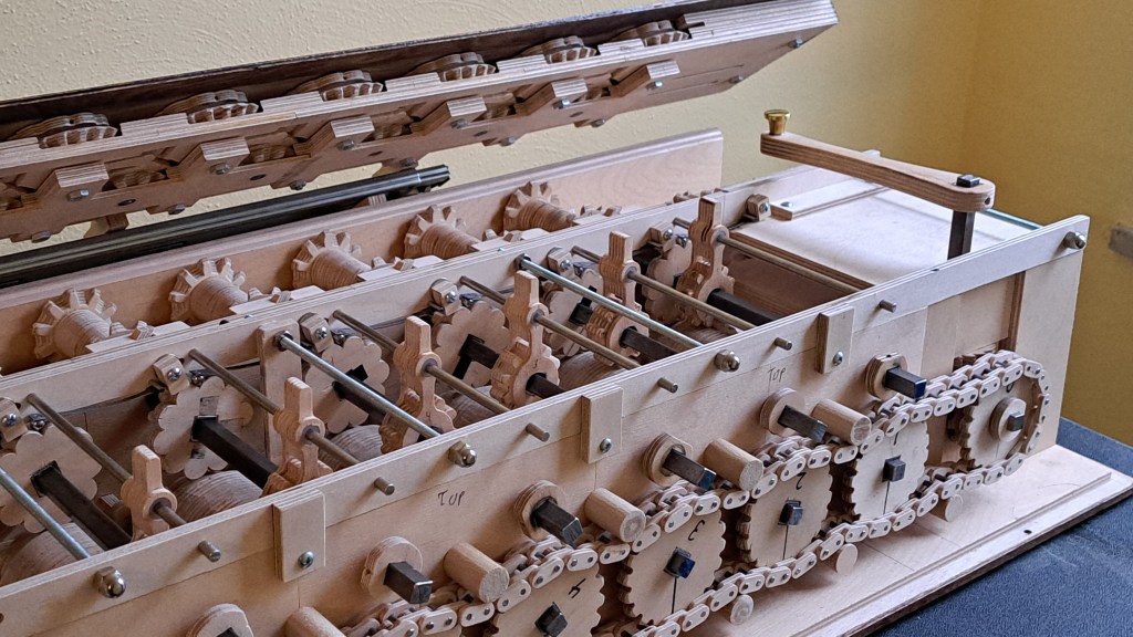
This is my homemade mechanical calculator. For the why and how it works, I made this video about it:
To give a little more about how I made it, I dug up old drawings I made of the parts. What follows is an explanation of making the calculator using those as a guide.
After studying pictures of the Arithmometer and other calculators (arithmometre.org proved very useful), I decided on the spacing between the shafts for the stepped drum and the corresponding 10-toothed gears to be 2 inches. This was based on what size gears I was comfortable with cutting, and it was imperial because I was in 8th grade and didn’t know better – I should say though that I doubt very much that Schickard, Pascal, or Leibniz used metric.
Knowing that distance, I generated a template for the stepped drum and 10 toothed gears using Matthias Wandel’s gear generator program.
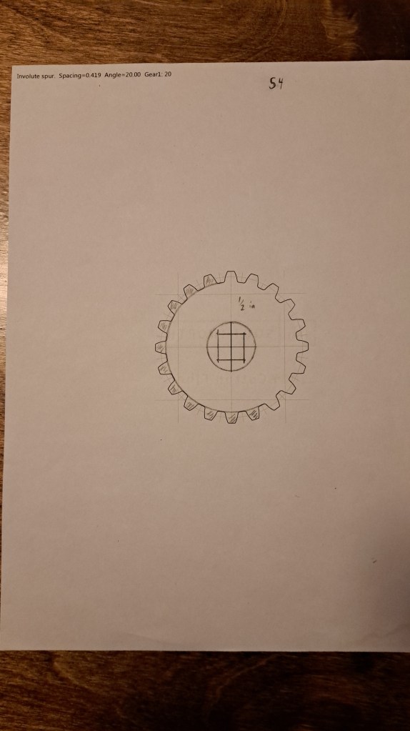
There’s the stepped drum. I shaded out 11 of the 20 teeth because we only need 1-9 for the stepped drum. I drew in the square hole because I landed on using 1/2 in. square tubes that fit and importantly slid nicely on 3/8 in. square shafts. As I show in the video, I then just glued that template to some plywood (1/2 inch baltic birch – the nice stuff) and cut the gears out on my scroll saw.
After experimenting with how to make bevel gears, I then generated these templates for the sets of bevel gears that translate the motion of the stepped drum mechanism to the output dials.

Matthias Wandel’s program also allows you to make a chain, which as I described in the video I decided to use for the power train instead of more bevel gears (which are tiresome to cut).
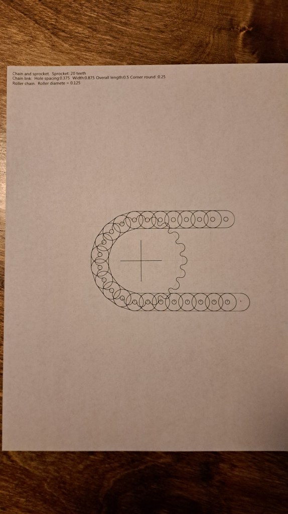
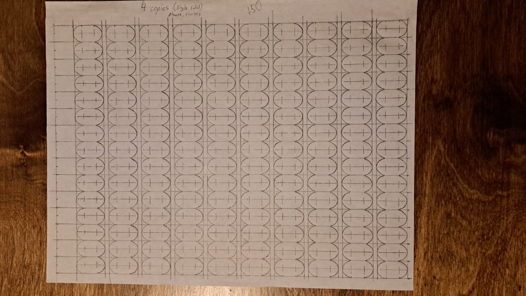
For the links I drew that template by hand then made copies. In hindsight, there was probably a way to make all the links in one or a couple of batches instead of individually.

At some point I made this (erroneous) list about all the parts I needed to make. I also drew out the diagram below.
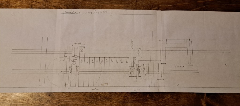
Clearly, though, that diagram was before I decided to use a chain for the drive (2018 according to the date).
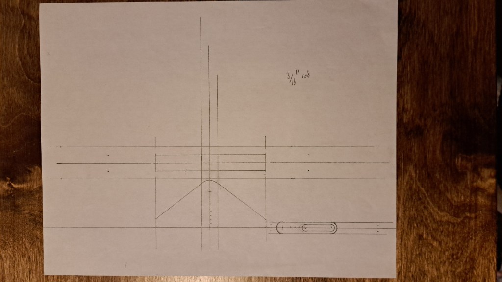
The extra tooth for the carry mechanism is exactly the same profile as the teeth in the stepped drums because I used the same template, seen below.

This template was also used to create the spiral ramp.
And I needed some discs with a square hole to build up the rest of the shuttle that the extra tooth and spiral ramp are on.
And there’s some hand drawings for the fork assembly that shifts the extra tooth.
Below is a fist draft for the sprung bracket that keeps the carry mechanism binary.
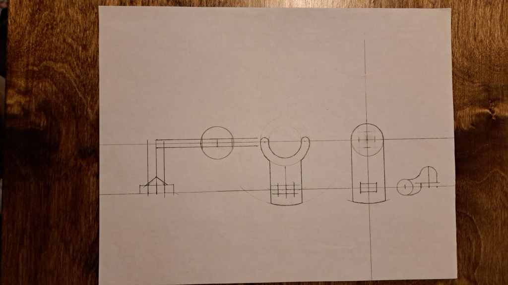
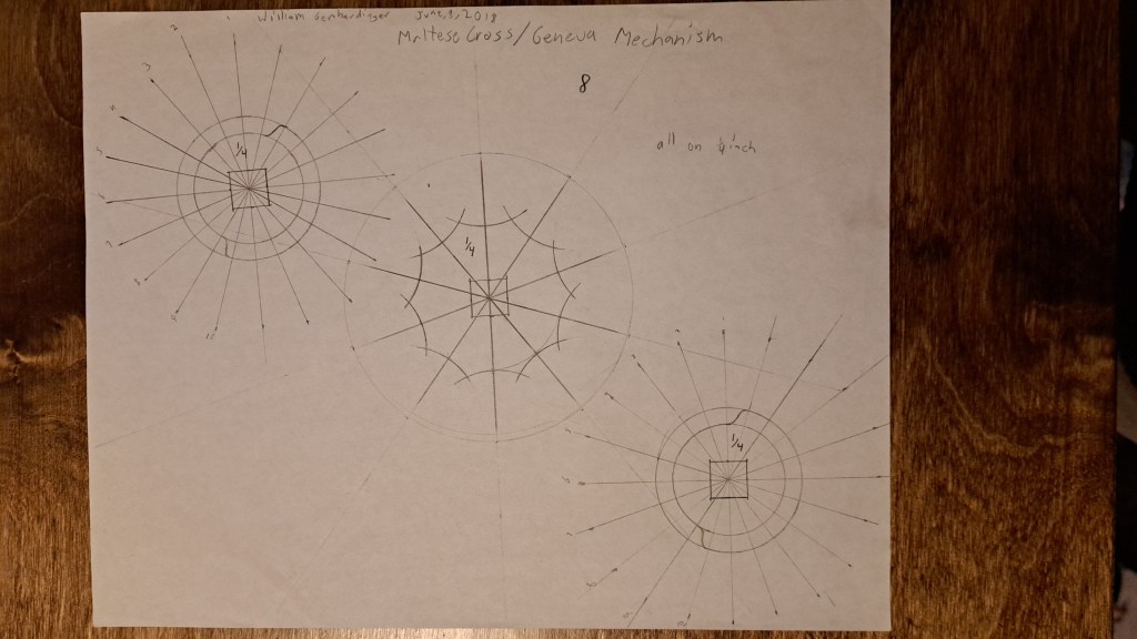
Those familiar with the Arithmometer will have noticed that my machine does not have the maltese cross or geneva mechanism that Thomas’ machine uses. The truth is I did try that mechanism, see the below picture of my drawings for it. But, I found it did not work satisfactorily so I switched to the ten-lobed wheels that interact with balls on leaf springs that I highlight in the video. I really do think that system is an improvement, it keeps things digital very nicely, and (as I say at the end of the video) allows fine tuning of where the teeth land after every jump.
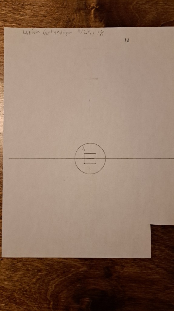
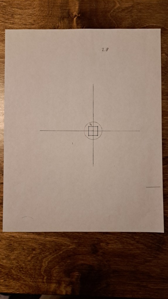
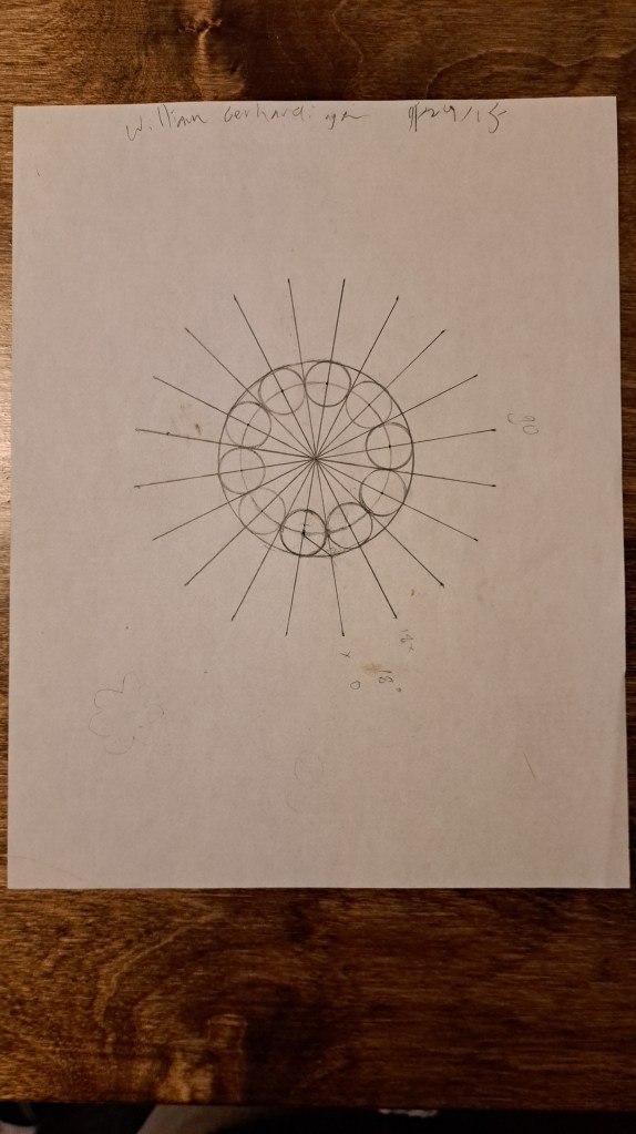
The below drawing, from 2015 when I was in 8th grade, was originally for a number dial, but I ended up using it for those keeping-it-digital discs that I just discussed.
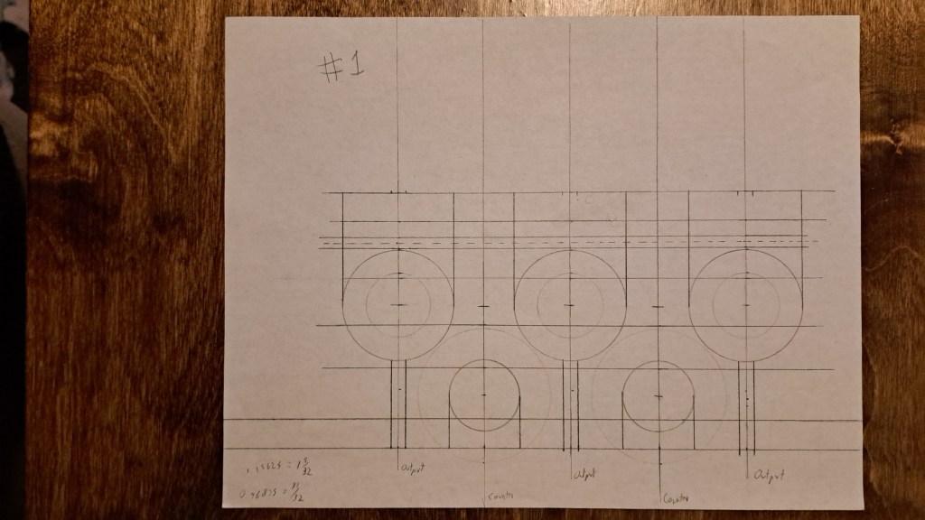
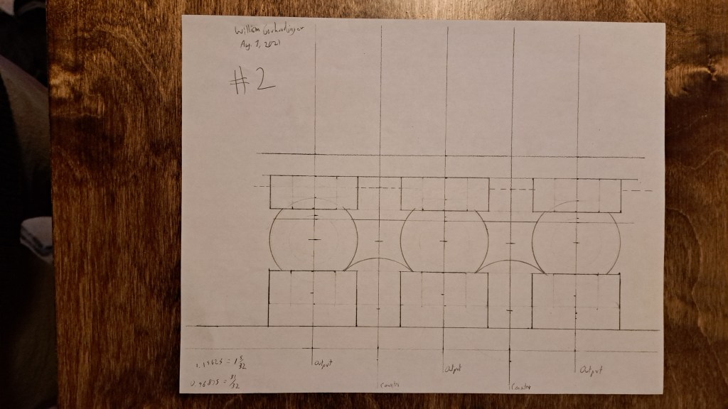
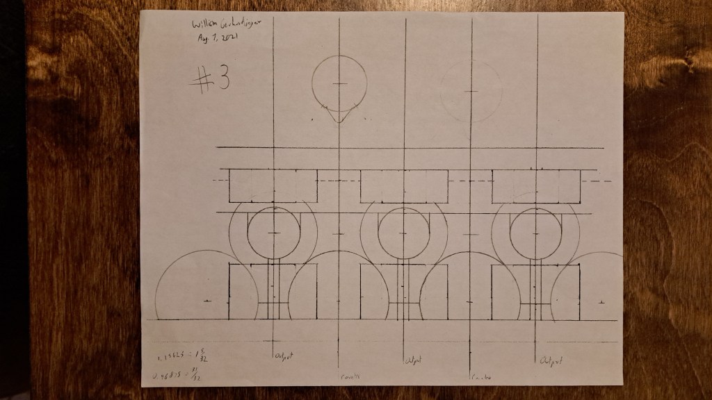
The results assembly proved to be the most difficult part. These first sketches show how I built it up in layers (for the diagrams, I literally made a copy of the previous layer then drew on top of it).
Eventually though I began to stretch the use-case of a paper, ruler, and compass and decided to use a 2d CAD program.
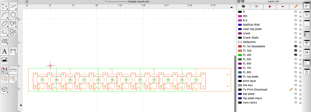
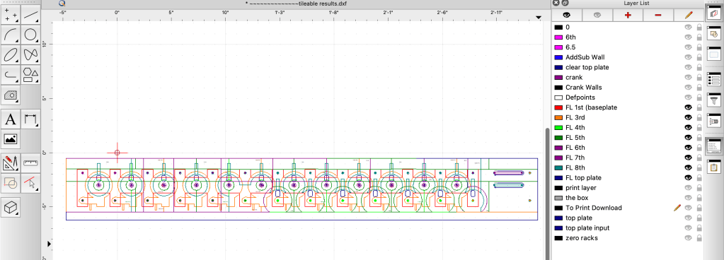
I only drew out the results assembly in CAD:
Baseplate
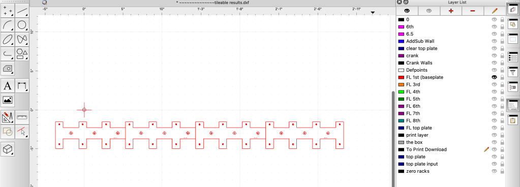
+ 2nd and 3rd layer
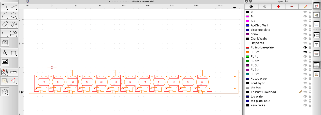
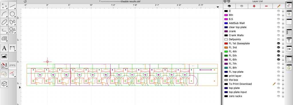
+4th layer
+ 5th layer

+6th layer
+7th layer
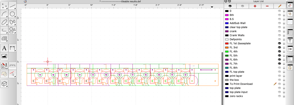
+8th layer
+ final layer (the cover)
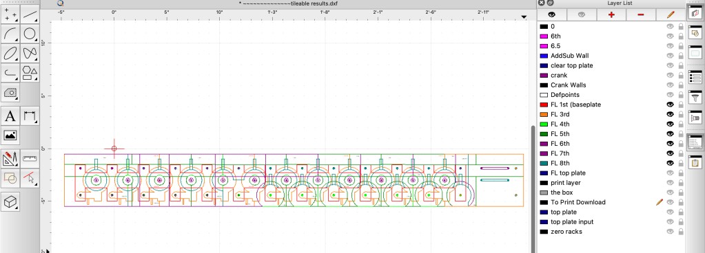
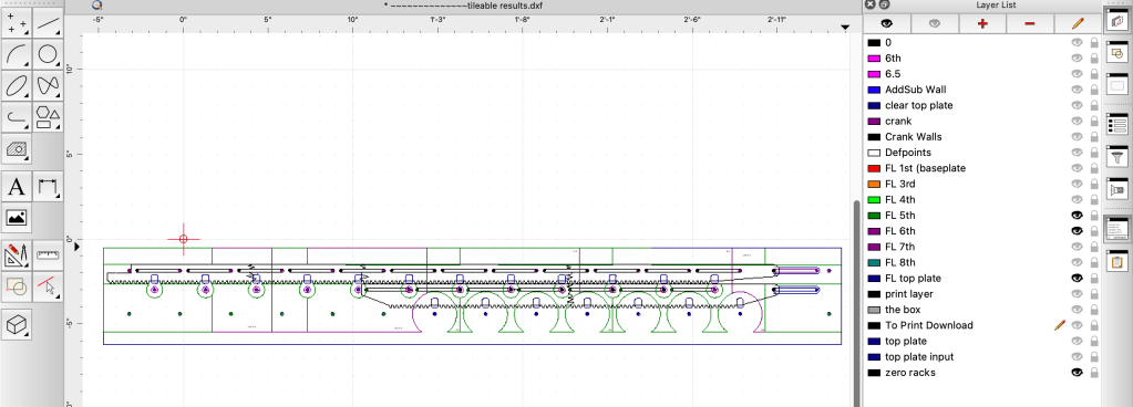
And here’s with just the 5th, 6th, and final layers, and the racks for zeroing the gears
Well that’s where my documentation runs out. There’s some simple parts I’ve glossed over like walls and panels, but those are the kind of things you can just draw out right on the material then cut, fit, and fiddle around till they work. To end, here’s what putting the calculator together looks like:
For more details, you can also see my other post about the calculator.
I do not have any plans available unfortunately.
Feel free to ask me any questions though and I’ll try my best to answer!

Leave a comment