This is an older post from before I finished the calculator. First watch this video:
When the ever-opitimistic Gottfried Wilhelm Leibniz hired the Parisian clockmaker Ollivier to materialize Leibniz’s design for a mechanical calculator in 1672, the philosopher payed the artisan a fixed sum for three weeks of work.
Instead, the two took forty years to produce a machine that never quite lived up to Leibniz’s Panglossian vision.
I have been working, on and off, for about eight. Here’s what I’ve got so far:
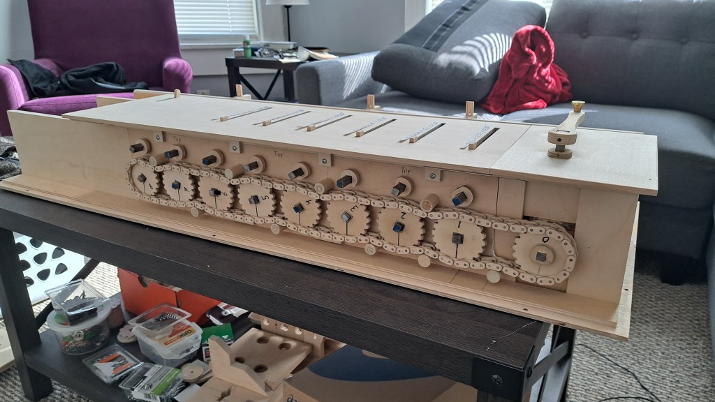
To perform arithmetic, numbers are entered using the sliders then added into the accumulator section at the top by turning the crank. For multiplication and division through repeated addition and subtraction, the accumulator portion also shows how many times the crank was turned. To aid in large multiplication and divisions the accumulator can be shifted over to the next (or more) decimal place – thus 412 * 55 is calculated in only ten crank turns.
My calculator is heavily based off Charles Xavier Thomas’ Arithmometer machines from the mid to late nineteenth century. Though Thomas’ machine bears similarities to Leibniz’s, the history of calculating machines should not be reduced to a linear progress narrative: see http://journals.cambridge.org/abstract_S0007087414000429.
The plywood is mostly high quality Baltic Birch. The round and square metal shafts are from Home Depot. All the gears, wheels, chains, cams, etc. were cut on a scroll saw. Other tools used were a drill press, table saw, hand planes, chisels, sandpapers, and woodworking lathe.
I have a lot I want to say materially, historically, and philosophically about this machine and mechanical calculators in general so expect more soon – but for now I’d like to go into some more detail about the parts of my calculator.
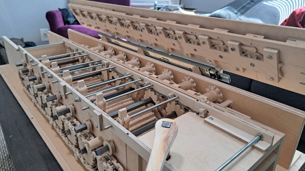
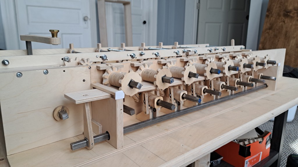
Drive Train:
Unlike the Arithmometer, or any mechanical calculator I’ve seen, I designed the main drive of my calculator to be a chain connecting 9 sprockets. So that a carry operation happens successively, like in the above video of 999999 + 1, and not all at once, each sprocket is one tooth (1/20th) offset from its neighbor to the right.
On the user input side, a simple crank with a pair of 90 degree bevel gears drives the chain. There is a ratchet, click, and clickspring to stop anyone turning the crank counterclockwise.
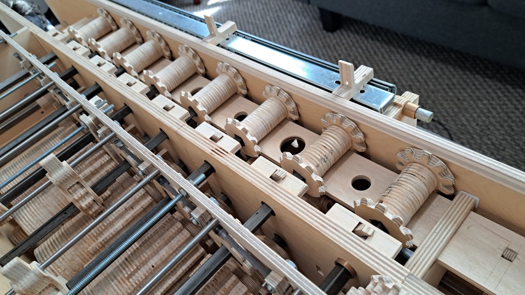
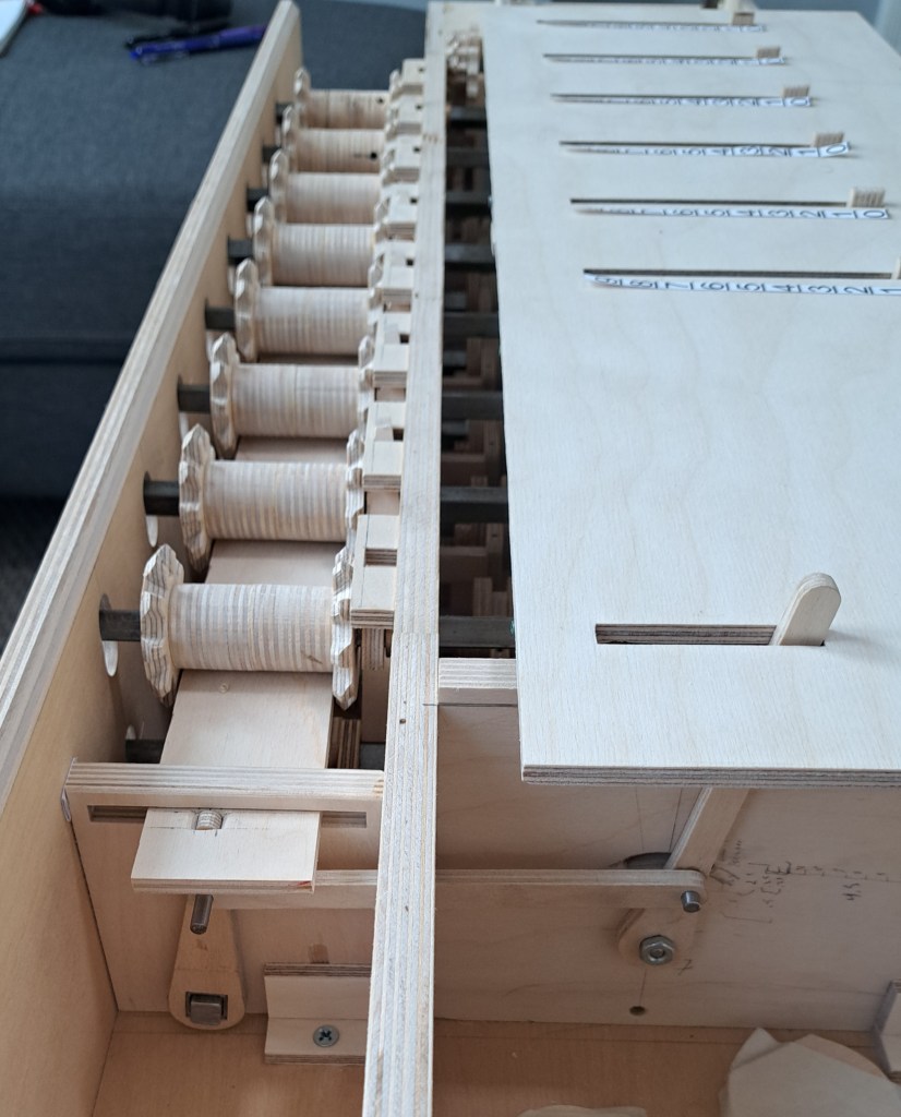
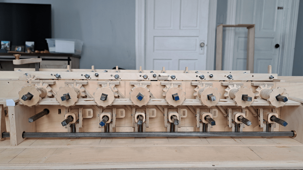
Inputs and Stepped Drums:
6 stepped drums (dubbed ‘Leibniz wheels‘) and their corresponding counting wheels lie at the heart of the machine.
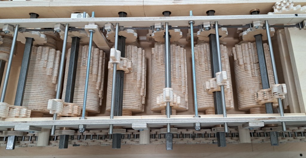
Bevel gears connecting counter wheels to the number wheels:
The stepped drums turn the counter wheels depending on the input, and this is shown to the user in the number wheels in the accumulator portion. To link the counter wheels to the number wheels there is a set of bevel gears.
Switching between Addition/Multiplication and Subtraction/Division:
Instead of somehow running the machine in reverse to perform subtraction/division, the machine simply takes the output from the counter wheel and switches the direction it rotates the number wheel. This is performed by shifting which bevel gear the number wheel meshes to.
A linkage assembly ensures all the bevel gears shift together from the flip of a lever on the top plate.
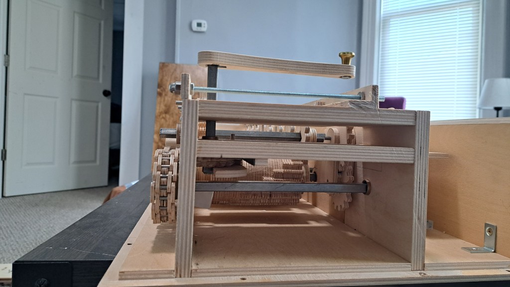
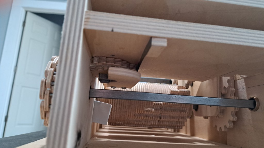
Carrying:
A carry is triggered when a wheel moves between 9 and 0 (or 0 and 9 in the case of subtraction) by a cam in the accumulator.
When the accumulator is set down into the machine, the cam trips a lever in the main body of the calculator that stretches diagonally from one column or decimal place to the next higher one.
The lever shifts an assembly on the square shaft that goes through the stepped drum of that column. On the assembly is one tooth with the same dimensions as those in the stepped drum. When a carry is triggered, the lever moves this tooth so that it meshes into a counter wheel. When no carry is triggered the tooth passes by the counter wheel.
Attached to the carry tooth assembly is a spiral ramp. When a carry is triggered, after the tooth has added the extra number, the ramp collides with a bump which pushes the assembly, and lever, back to their normal positions. This resets the whole carry operation.
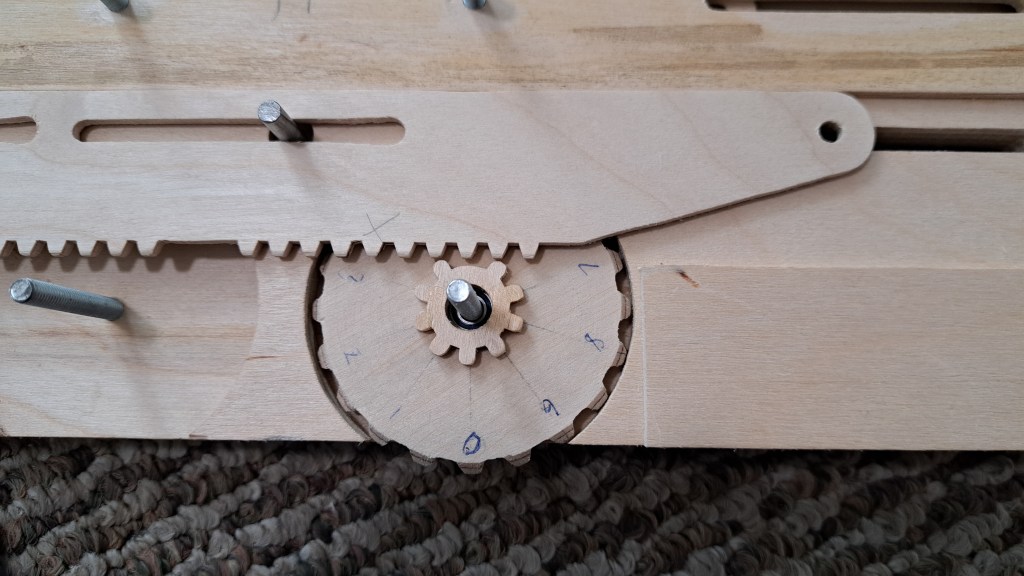
Multiplier/Divisor:
To allow multiplication and division through repeated addition and subtraction, the calculator displays how many times the crank was turned. This is simply a gear train attached to the first column that, using a bevel gear, changes 1 rotation of the crank and sprockets into 1/10th of a rotation of a number wheel.
Zeroing:
Within the accumulator, the product number wheels and multiplier number wheels all contain a gear with 10 teeth. Except, one tooth has been removed so that when a rack is pushed into these gears, they stop at the missing tooth. By chance, the missing tooth corresponds to the zero position of that number wheel.
It’s very satisfying when it zeros all the windows.
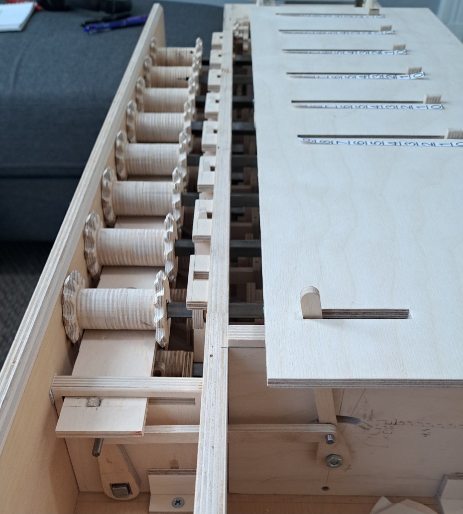
Sliding the Accumulator:
To shift the decimal place, and thus multiply and divide large numbers quickly, the accumulator sits on a hinged drawer slide.

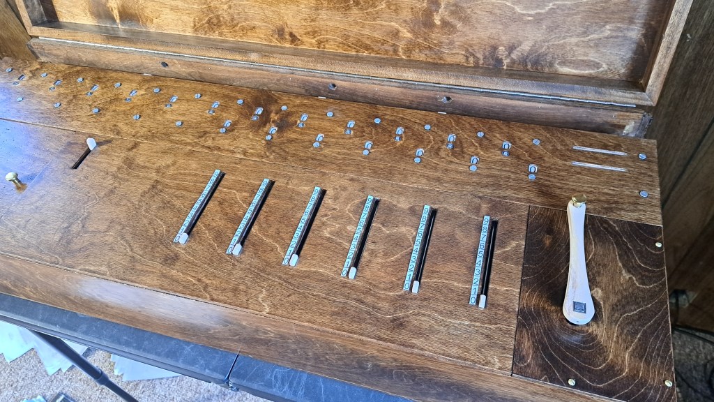
The Case:

Finally, I’ve made a simple case and stained the outer panels to a darker shade to give it more gravity.
I have not discussed here many of the trickiest bits of the mechanism, which were the springs and devices to keep the machine digital, so to speak. There are several features which ensure a gear always fully rotates by a tooth, or that keeps a number wheel on a number and not in between numbers. These are very critical to the machine working well, and I plan to discuss them in a video when the calculator is complete.
Expect a video soon showing the mechanism better, detailing my process of making it, and getting into some history and philosophy!
Extra resources:
Arithmeum in Bonn, Germany

Leave a comment